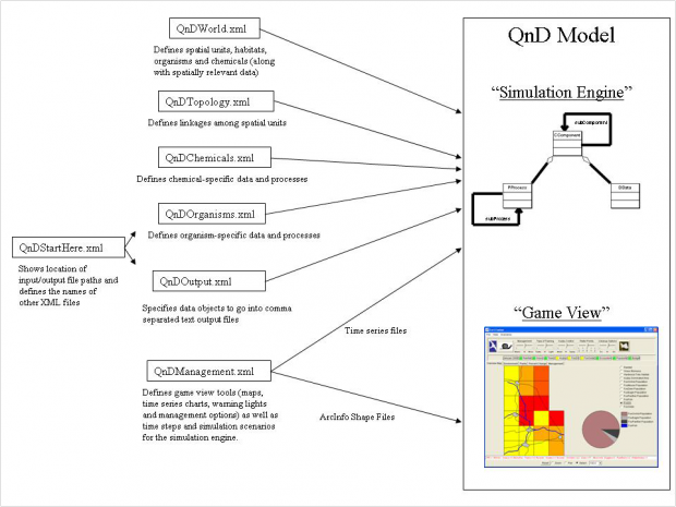
Each version of QnD is created entirely from the XML file inputs. Figure shows the input files and their use to create the QnD Simulation Engine and Game View. The QnDStartHere file is read by QnD to find the input and output file paths as well as the exact filenames of the other XML files.
QnDWorld

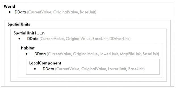
The QnDWorld file is read to construct the various spatial units along their constituent habitat and local component objects. Any DData objects that represent spatially unique properties are included in the QnDWorld file. It defines the frame of the problem, simply sets up what is going on the world (how many of things and how things are structured). There are no dynamics in this file, only structure. It contains the Global or World DData and the n SpatialUnits. Inside each SpatialUnit, some DData and one or several Habitats are defined, and again, inside each Habitat some DData and one or several CComponents are defined. Finally, each CComponent contains some DData.
QnDComponentDetails
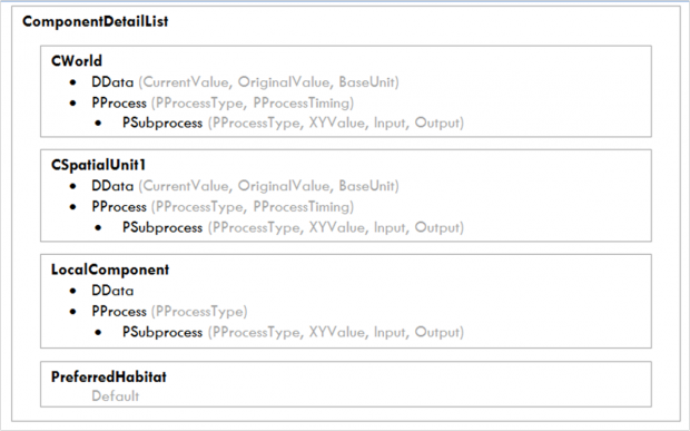
This file sets for each Ccomponents, which are as a hierarchy (CWorld, CSpatialUnit, CHabitat, CLocalComponent), and their DData and PProcesses. The structure of the file is the showed in the figure. This XML file is where all the action is. Processes can be defined at global, spatial unit, habitat or localComponent levels. Running time “early” or “later” and process type “PProcess”, should be define for each PProcess. Processes comprisse one or more subprocesses. Also subprocess type (relationship, divide, add, multiply, etc.), input and output DData used, need be defined for each subprocess. The subprocess type is defined and implemented in QnD Control package in the simulation engine as PSetValue, PRoundValue, PSubstractValue, PAddValue, etc.
QnDManagement
This file has both time series (date and timed steps used are defined) and external driver (showed in csv input files) configurations along with all the user interface “widget” maps and charts and warning lights (the different ways for GUI are also included here). This can define also the management options and the geometry of the study site.
QnDTopology
The QnDTopology file is used to link various spatial units with each other. Any connections can be put here, not just spatial neighbors, even spatial units in another spatial areas can be connected, naming a new “linkage” and then using the description name in various processes. This allows a large amount of freedom beyond simple neighbor operations. However, in simplest cases, connections will be between spatial neighbors.
QnDOutput
The QnDOutput.xml file is read to create user-defined files of DData values in a comma separated text format. Any DData in QnD at any level can be output in a comma separated file.

